
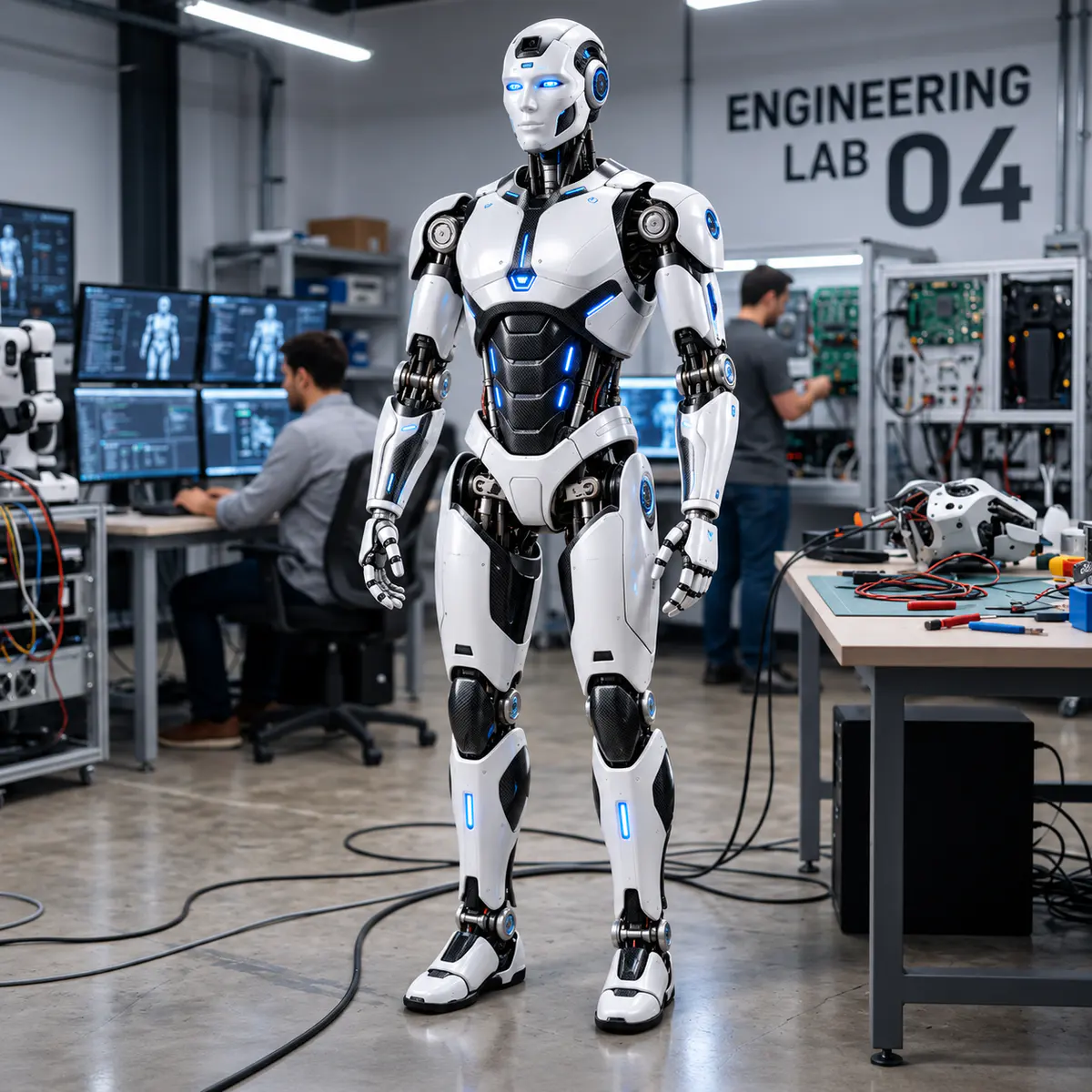
A humanoid robot combines structures, actuators, power electronics, sensors, communications and software within a tightly constrained physical system. A component can perform well in isolation and still fail at system level because its interfaces do not match the needs of the surrounding subsystems.
Compatibility therefore needs to be evaluated as an engineering discipline, not left until final assembly. The following approach helps a prototype team make interface assumptions explicit and test them progressively.
Begin with system-level use cases
Define the motions and operating conditions the prototype must support. Standing, walking, reaching, object manipulation and teleoperation place different demands on torque, speed, sensing, latency, power and thermal performance.
Convert each use case into measurable system requirements. These may include range of motion, payload, cycle time, stability margin, operating duration, environment and safe-state behavior. Without this baseline, a subsystem can only be judged against its own specification.
Create an interface control model
For every subsystem boundary, record the mechanical, electrical, communication and software interfaces. An interface record should identify connector and pin definitions, voltage ranges, current demand, message formats, update rates, coordinate frames, timing assumptions, fault behavior and responsible owner.
Treat mass, heat and space as interfaces too. A heavier hand changes arm inertia and joint demand. A high-current actuator changes battery, cabling and cooling requirements. A camera position affects structure, field of view and calibration.
Check the mechanical chain
Verify dimensions, mounting patterns, tolerances, fasteners, cable paths and service access. Examine the complete load path rather than only the rated output of an actuator.
Joint torque calculations should consider link mass, payload, acceleration, leverage, friction and an appropriate engineering margin. Also assess gearbox backlash, structural deflection and impact loading because these can affect control performance even where static strength is adequate.
Use a mass and inertia budget for each limb and keep it current as components change. Small additions far from a joint can materially increase dynamic demand.
Build a power and thermal budget
List nominal, peak and transient current for actuators, computers, sensors and communication hardware. Compare these demands with battery capacity, discharge limits, converters, protection devices, connectors and conductor sizing.
Average power alone is not sufficient for dynamic motion. Simultaneous joint acceleration can create short peaks that cause voltage drop, controller resets or protection trips. Bench tests should reproduce realistic combined loads.
Thermal compatibility matters as well. Document heat sources, expected duty cycles, temperature limits, sensing and cooling paths. Test enclosed assemblies because bench behavior in open air may not represent the final installation.
Validate communications and timing
Map every device onto the proposed network and estimate traffic under expected update rates. Check addressing, bandwidth, message priority, synchronization, error recovery and physical topology.
Control performance depends on latency and jitter across sensing, computation and actuation. Measure the end-to-end loop rather than relying only on a network’s theoretical speed. Define what the robot should do when a message is delayed, lost or invalid.
Align sensing, coordinates and calibration
Sensors need compatible electrical interfaces, sampling rates, mounting stability and data representations. Define coordinate frames and units consistently across mechanical design, firmware and higher-level software.
Develop calibration procedures alongside the hardware. Encoders, inertial sensors, force sensors and cameras may each require reference positions, transformations or compensation. Store calibration data with clear version control so a hardware change does not silently invalidate it.
Define software and safety contracts
Specify the command, state and diagnostic information exchanged between software layers. Version message definitions and configuration files. Confirm that limits in planning software agree with the physical joint range and lower-level controller settings.
Safety behavior should cross subsystem boundaries. Emergency stop, power isolation, joint limits, watchdogs, thermal protection and controlled shutdown need a defined response from hardware and software. Test faults deliberately in a safe setup.
Integrate through progressive test stages
Move from component tests to joint modules, limbs, a supported full body and finally dynamic trials. Establish acceptance criteria at each stage and record the configuration used for every test.
A practical sequence is:
- verify component identity and basic specifications;
- test electrical and communication interfaces on the bench;
- characterize an integrated joint module under representative load;
- validate each limb’s motion, sensing and limits;
- integrate the body with external support and constrained power;
- test coordinated motion and fault responses; and
- expand the operating envelope only after reviewing evidence.
Compatibility is not a one-time checklist. It is controlled evidence that each interface still works as the design evolves. Maintaining interface records, budgets and staged tests gives a humanoid robotics team a clearer route from promising components to a coherent prototype.
Editorial review: Reviewed by AFAQ Editorial Team. Last reviewed September 9, 2026.